Rooftop Flying Crank Ghost – Part 1
Haunting November 13th, 2007The “Flying Crank Ghost” has become a popular prop to build amongst home haunters. There are plenty of instructions on the Intertubes on how to build them, but I decided to go a slightly different direction with mine. I wanted it to be more cartoony and ethereal than most. It also had to be pretty big because I wanted to put it on my roof. Also, I wanted to be able to adjust the motion fairly easily without having to drill new holes each time. It turned out pretty well, so now I’m going to show you how you can make your own Scott-style cartoony roof flying crank ghost.
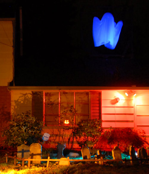
Parts you need
- 1x 18″ transparent ball half (Display and Costume Supply)
- 2x 9″ transparent ball halves (Display and Costome Supply)
- 15′ x 54″ Piece of White Chiffon (Display and Costume Supply)
- Laundry Detergent or Bluing (The grocery store)
- 3x Tiny Keyrings (Michaels or wherever they sell bead stuff)
- 1x 3/4″ x 36″ plated steel stock (Lowes, Home Depot)
- 1x Grounding Clamp (Lowes, Home Depot)
- 1x 5/16″ x 2″ x 3″ Square “U” Bolt (Lowes, Home Depot)
- 5x 3/8″ x 1 1/2″ Fender Washer (Lowes, Home Depot)
- 10x 2″x4″x8′ Stud (Lowes, Home Depot)
- 4x 1″x4″x8′ (Lowes, Home Depot)
- 4x Can of Flat Black Spray Paint (Lowes, Home Depot)
- Assorted Length Wood or Drywall Screws (Lowes, Home Depot)
- 6x 1/4″-20 x 3″ Eye Bolt (Lowes, Home Depot)
- Assorted Washers (Lowes, Home Depot)
- 2x 1/4″ Nylon Lock Washers (Lowes, Home Depot)
- 3x 1 1/2″ Screw Link (Lowes, Home Depot)
- 3x 1″ Swivel Pulley (Lowes, Home Depot)
- Clothesline – Choose a thickness that will fit through your pulleys and not slip beside it (Lowes, Home Depot)
- 1x 3/16″ Wire Clamp (Lowes, Home Depot)
- 4x 2″ “L” Bracket (Lowes, Home Depot)
- 4x 10-32 x 1/2″ Pan-Head Machine Screw (Lowes, Home Depot)
- 2x 3/8″ x 6″ Hex-Head Bolts (Lowes, Home Depot)
- 2x 3/8″-16 Nuts (Lowes, Home Depot)
- Extension Cords
- 1x Power Cord (Cut off of your tape deck; nobody uses analog any more)
- Electrical Tape
- Wire Nuts, Butt-Splice Crimp Connectors or Solder (choose your poison)
- Giant Blacklight
- Flying Crank Ghost Motor
Tools you need
- Drill
- Drill Bits
- Crescent Wrenches
- Hack Saw
- Crimp Tool or Soldering Iron
- Screw Gun
- Ladder
- Sewing Machine
Support Frame and Mechanical Construction
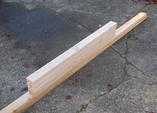
First we need to build the top frame that supports everything. Grab 4 2x4s. Cut 2 of them in half so you end up with 4 4′ sections and 2 8′ sections.
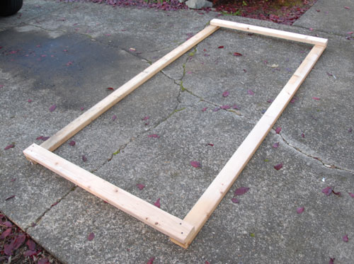
Screw a pair of 4′ and a pair of 8′ boards together to make a rectangle. Make sure the short ones are on what is going to be the top.
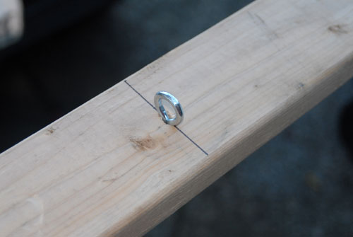
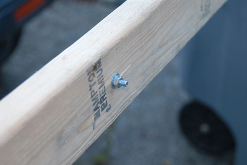
Install 3 eye bolts into the 8′ side that is going to be the front of the frame with the eye end down. The first should go in the center and the others should be 24″ from center. Use the included nuts and a washer to tighten them down.
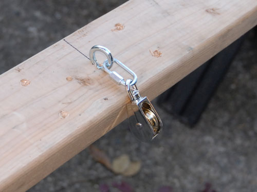
Attach the 3 pulleys to the eye bolts using the 3 screw links. You should end up with this:
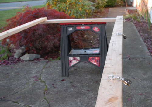
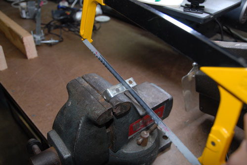
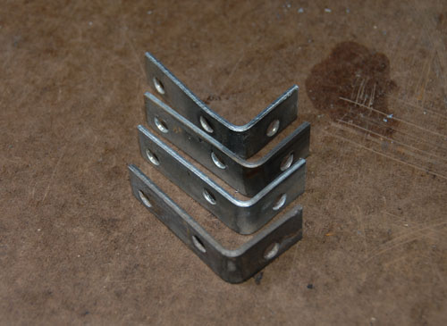
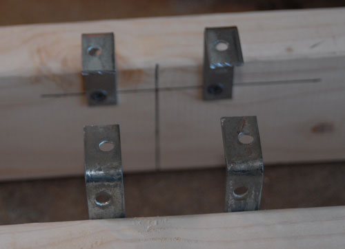
Now we need to mount the motor to the 2 remaining 4′ boards you cut. First take your 4 “L” brackets and cut one end of each in half (we do this because they will run into each other later if we don’t and we’re only using one hole anyway).
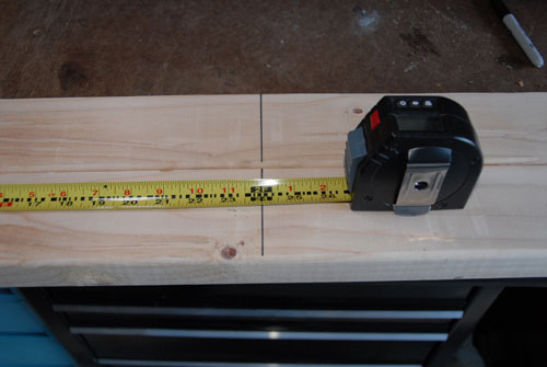
Mark the center of the 2 4′ boards.
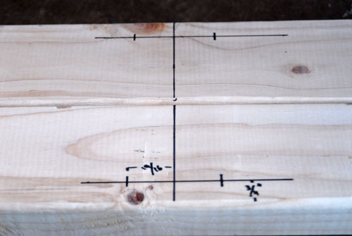
Mark 2 points on one board 1/4″ from the edge and 19/16 from the center line.
Do the same thing on the opposite edge of the second board
Screw the 4 “L” brackets to the boards using the screw locations you just marked. Make sure you attach the longer sides of the brackets to the boards.
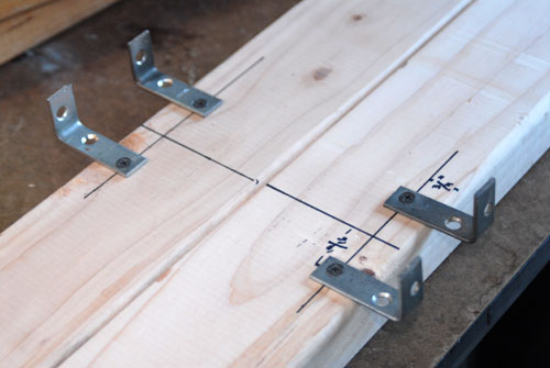
Tip the boards up so that the brackets are sticking up from the top.
This would be a good time to attach a power cord to the two wires coming out of your motor. Use crimp-on butt-splice connectors, solder, wire nuts or whatever you have handy. Please don’t just twist the wires together. Promise me you won’t be that ghetto.
Make sure you insulate the connection well. Electrical tape or heat-shrink tubing will work nicely.
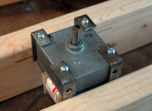
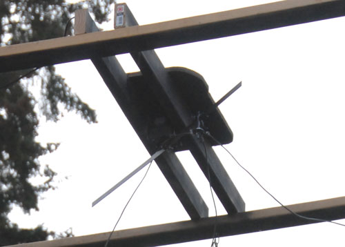
Attach the motor to the brackets using the 4 10-32 x 1/2″ screws and some split washers. Note: if you’re using a different motor then you may have to modify the above motor-mounting instructions. The idea is to attach it to the two boards and have it protruding from the bottom enough that the arm assembly doesn’t hit anything.
Screw the motor support assembly to the center of the rectangular frame you built earlier. Make sure it goes on what is to be the top of the frame (You’ll want to attach it while it’s upside-down). Note: The ends of the 4′ boards may not line up exactly with the edges of the 8′ boards since the holes in your “L” brackets probably weren’t centered.
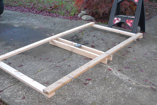
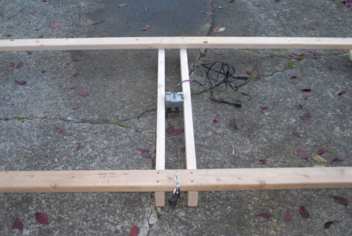
Install a cover over the motor. I used a piece of scrap plywood but you can use a cookie sheet, garbage can lid, nacho platter, umbrella (ella ella) or whatever. The idea is to keep the motor dry if it rains.
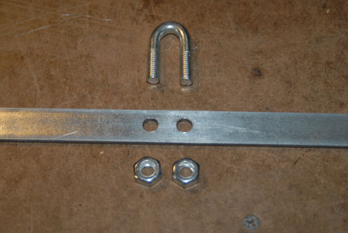
Now we need to attach the steel bar to the motor shaft. Take the wire clamp and discard the saddle part. Drill 2 holes in the center of the bar of the proper size and spacing to allow the two ends of the U-bolt part of the cable clamp to fit through (my holes were 5/16″ but yours may be different depending on the clamp).
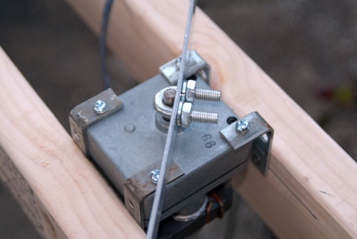
Attach the bar to the motor shaft with the U-bolt, making sure the flat side of the shaft is up against the bar. Make sure there is a bit of space between the motor and the bar so they don’t rub on each other. Use split washers, and tighten the nuts as tight as you can before the bar starts bending.
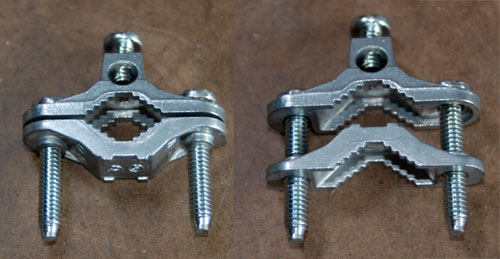
Next comes the clamp assembly. Take the grounding clamp and flip one side of it around so that the two halves nest into each other.
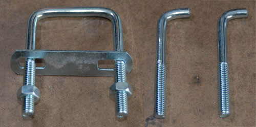
Take the nuts and metal bar off of the square U-bolt. Measure the width of the grounding clamp. Now make a cut in the top of the U-bolt so that the piece ends up as wide as the grounding clamp (mine ended up being 3/4″ from the inside of the bend to the cut end). If you want two of these assemblies cut the second half to the proper width too.
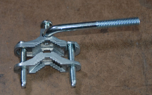
Place the stubby top end of the U-bolt into the wire hole of the grounding clamp, adjust so that it is at a right angle to it, and tighten the screw.
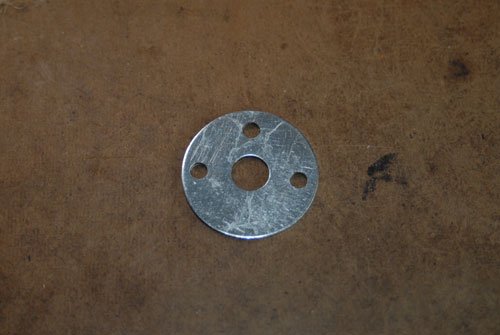
Drill 3x 3/16″ holes in a 3/8″ x 1 1/2″ fender washer in a 180-degree arc.
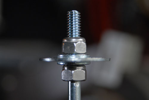
Install the washer onto the threaded end of the U-bolt half. You basically want to make a sandwich in the order of lock nut, small washer, fender washer with holes, small washer, lock nut. Tighten the final nut down enough so that the fender washer doesn’t wobble but can still spin freely.
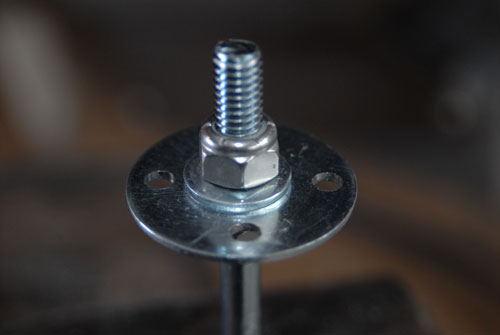
Insert a ring into each of the 3 holes in the washer. Here’s what the finished assembly should look like:
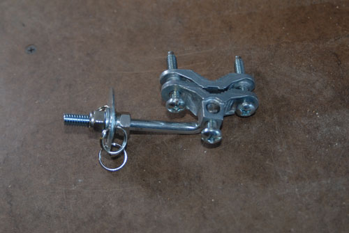
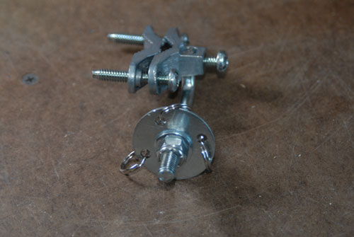
Clamp the washer assembly to the steel bar about 3/4 of the way to the end (you can adjust this later) and tighten the screws. The washer will eventually end up below the bar, so make sure you attach it the right way (the whole thing is still upside-down in the picture).
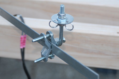
With the frame upside-down, install the legs. Take a couple of 8’x2″x4″s and screw them to the two ends of the frame, in the middle, sticking straight up. Make sure they are at right angles to the frame.
Use 2 1″x4″ boards to connect the back of the frame to the center of the legs. This is one of those steps that’s easier to show you then tell you about, so on to the picture:
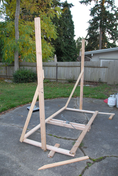
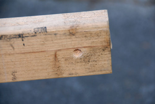
Drill a 1/2″ hole in the other end of each leg (the end that will be the bottom), centered and 1 3/4″ from the end.
Next come the feet. The purpose of the feet is to create and adjustable-angle base for the entire assembly that will rest flat for testing on the ground and conform to the angle of the peak of your roof when it comes time to install the ghost.
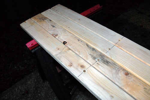
For the feet you’ll need 4 more 8′ 2″x4″ boards. Drill a centered 1/2″ hole 2 feet from one end of each one.
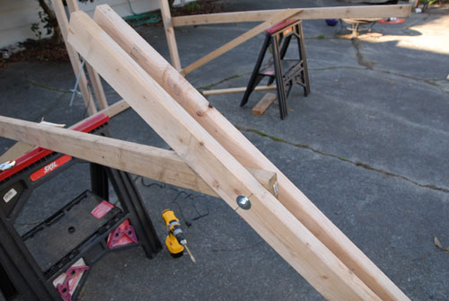
Use 3/8″ x 6″ hex head bolts and some fender washers to attach the feet to the legs. Put one foot on each side of each leg. Tighten the nuts down enough that the feet are difficult but not impossible to move by hand.
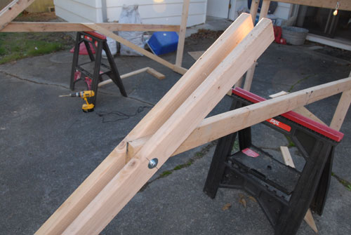
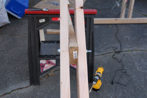
Stand the entire assembly up, laying the feet down flat as you do so. Have a friend hold the top part up straight while you screw some blocks in between the feet and legs so that the whole thing doesn’t tip over while you are working on it.
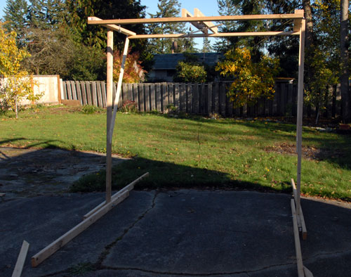
The support structure and mechanical portions of your ghost are finished. Continue on to Part 2 to find out how to make the ghost itself and install everything on your roof.


December 8th, 2011 at 12:41 AM
Hello very nice website!! Man .. Beautiful .. Amazing .. I will bookmark your web site and take the feeds also…I am glad to search out so many helpful info right here in the put up, we want develop more techniques on this regard, thank you for sharing. . . . . .
January 23rd, 2012 at 12:00 PM
Thanks a lot for giving everyone an extraordinarily special opportunity to discover important secrets from this site. It is often so lovely and packed with a good time for me and my office colleagues to visit your web site at a minimum three times weekly to study the latest issues you will have. And of course, we’re usually fulfilled with the tremendous methods served by you. Certain 1 facts in this post are basically the most efficient we have ever had.
March 8th, 2012 at 9:25 AM
It’s appropriate time to make some plans for the future and it’s time to be happy. I’ve read this post and if I could I want to suggest you few interesting things or suggestions. Maybe you can write next articles referring to this article. I wish to read even more things about it!
December 9th, 2012 at 4:08 PM
I have read so many articles or reviews on the topic of the blogger lovers except this article is truly a nice post, keep it up.|