Overclock your Nintendo DS Lite
Game Boy April 16th, 2007This article shows how you can overclock or underclock Nintendo’s latest handheld console, the DS Lite. The mod allows you to switch between four different speeds, ranging from .66x to 1.8x, right in the middle of your game. The wireless even works no matter what speed you are running. You can use a combination of the DS’ own buttons to control the speed so there’s no need to mount any external controls and mess up the look of your DS. The power LED will blink to tell you which mode you are in.
Why would you want to change the speed of your DS? Unlike regular computers and some other game systems like the PSP, DS (and GBA) games always expect the handheld to run at exactly the same speed. When you speed up or slow down the clock, the game speeds up or slows down. This is great for making your games harder or easier. It’s also useful for squeezing some extra clock cycles out of the hardware so you can make more powerful homebrew apps. You can also show off how L33T you are to your friends if you are into that sort of thing (or if they even care).
What you need:
- Nintendo DS Lite
- GBAccelerator DS overclocking chip
- Tri-Wing Screwdriver
- Small Phillips screwdriver
- 30 AWG kynar wire-wrap wire
- Low-wattage, fine-tipped soldering iron
- Solder wick (desoldering braid)
- Fine, rosin-core solder
- Wire cutters
- Wire stripper
- Needle-nose pliers
- Electrical tape
- Double-sided tape
- Utility Knife
- Cup or bowl to contain parts
Take the DS Lite Apart
Turn the DS Lite upside down. Use a phillips screwdriver to remove the battery cover.
Remove the battery.
Remove the stylus.
Remove the GBA cartridge hole plugger thingy.
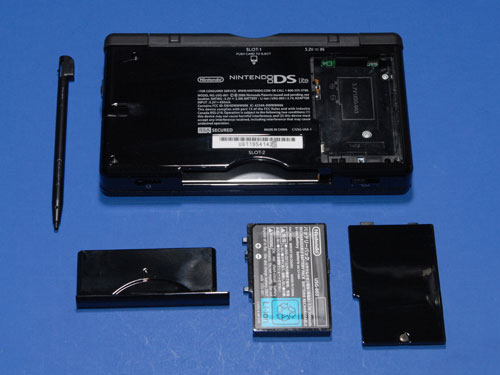
Use a Phillips and a tri-wing screwdriver to remove the eight screws from the back of the DS. Note: two of the screws are hidden under stick-on rubber feet. Use a utility knife to carefully peel them off so you can access the screws underneath. Try to set the feet somewhere where they’ll stay sticky.
Put the screws in your parts container or you will never see them again.
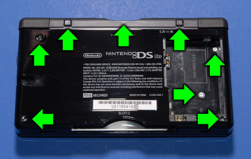
Lift the back cover off of the DS. The bottom edge may need a little prying, but it should just snap apart.
Carefully remove the L and R buttons if they haven’t popped off and fallen on the floor yet. Be careful when doing this; the pin and spring in these buttons fall out very easily and are easy to lose. Put them in your parts container when you find them.
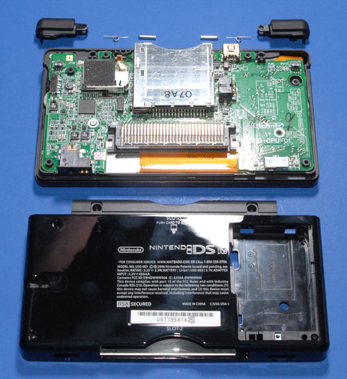
There should be one screw left holding the PCB in place. Remove it.
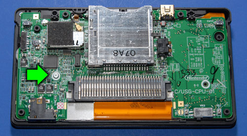
Disconnect the black antenna wire from the RF module and pull it out from under the game slot assembly.
Disconnect the white microphone wire from the PCB near the RF module and bend it out of the way.
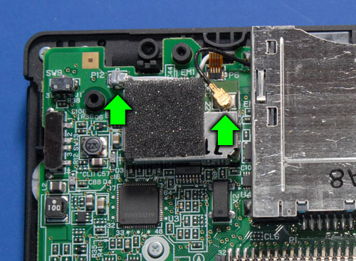
Disconnect the small ribbon cable from the connector near the RF module. Do this by flipping the black part of the connector up and sliding the ribbon out.
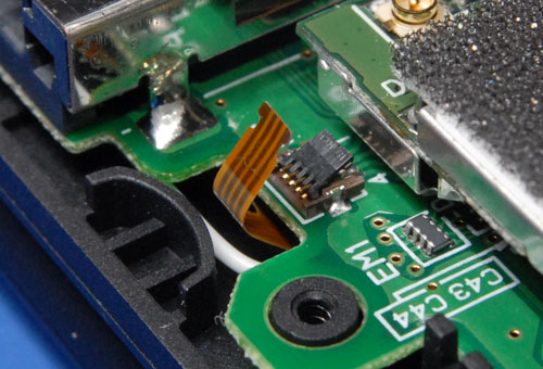
Flip the PCB and LCD screen together up out of the case. They will hinge on the ribbon cable that goes to the top screen.
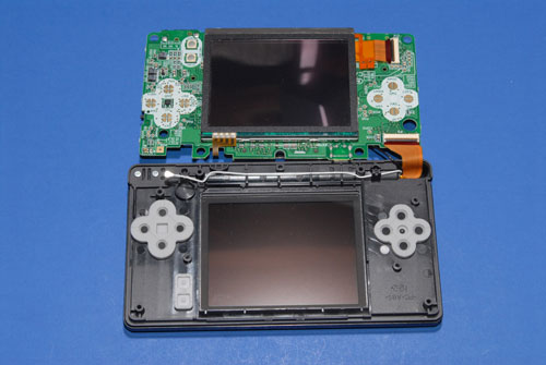
Disconnect the remaining two ribbon cables. Do this by flipping the dark-gray part of the connectors up and sliding the ribbon out.
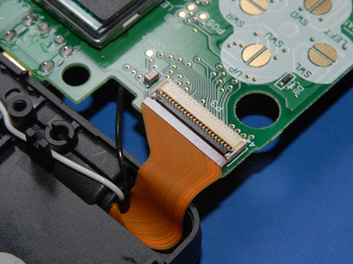
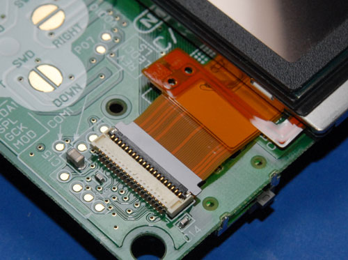
Place the LCD touch screen back in the case and set them aside. Now you have the PCB separate from the rest of the DS so you can work on it.
Pull straight up on the RF module until it comes free of the PCB. Set it aside.
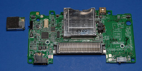
Remove the Existing Crystal
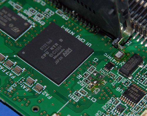
There are four metal tabs that hold the game slot assembly onto the PCB. Desolder these. Solder wick is probably the easiest, but use whatever solder kung-fu works for you.
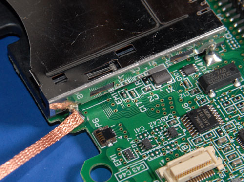
Lift up on the slot assembly. It will swing back on the pins which are still attached to the PCB. Now you have easy access to cryxtal X1.
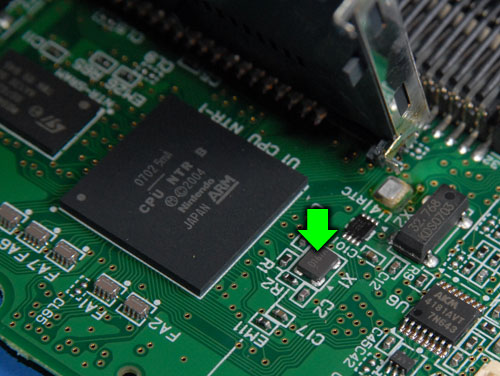
Desolder and remove the crystal. If you mangle it that’s okay since you won’t ever need it again.
Attach a wire to one of the solder pads where the crystal used to be. This diagram shows you exactly which one:
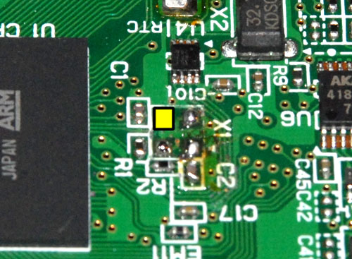
Bend the slot assembly back into place and re-solder it to the PCB.
Install the GBAccelerator DS
Flip the PCB over so that the front side is facing up.
Solder the three button wires (blue in diagram) and the LED wire (green in diagram) to their respective solder points. Route the wires across the board as shown in the diagram. This is important so that they don’t interfere with any buttons, standoffs, etc. Let them hang off the edge for now.
|
GBAccelerator DS Lite Front Connections
|
|
| LED | Green |
| BUTTON | P02 |
| BUTTON | P08 |
| BUTTON | P09 |
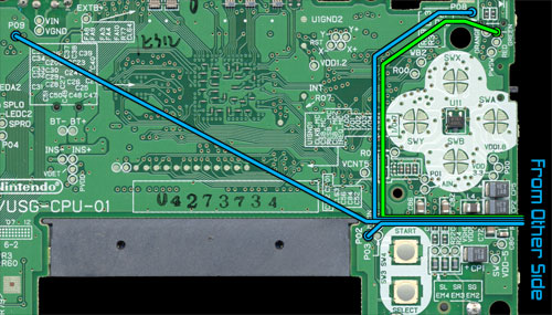
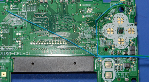
Lay the board next to the top half of the case.
Reconnect the ribbon cable that goes to the top screen. Note: the ribbon connectors in the DS Lite don’t slide back together very easily. Make sure you slide the ribbon all the way in before flipping the latch back down or DS won’t even boot.
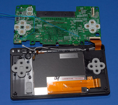
Lay the LCD touch screen on the PCB and reconnect its ribbon cable.
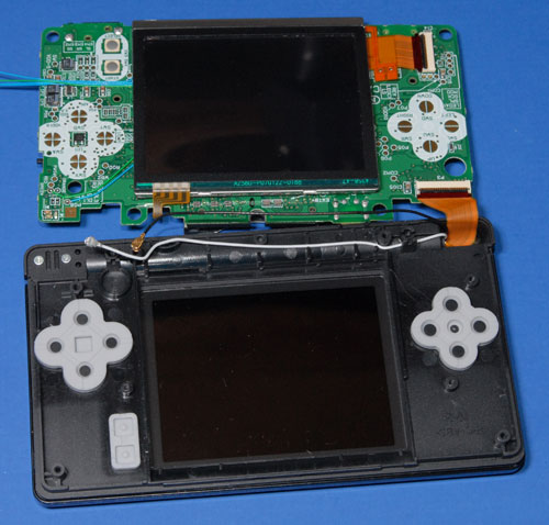
Flip the LCD/PCB combo over into the top half of the case. Make sure the screen lines up with its opening. As you lower the board into position the tuft of wires you connected to the other side of the board should bend up and around the edge of the PCB.
Reconnect the small ribbon cable and the white microphone wire.
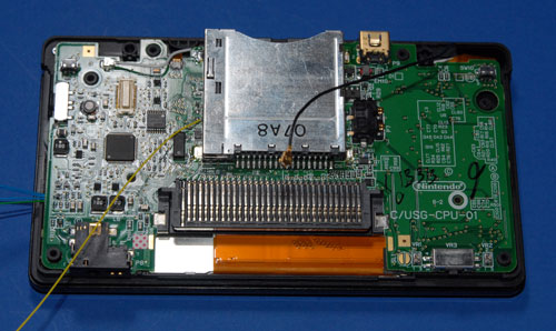
Replace the screw that held the PCB into the top half of the case.
Use double-sided tape to stick the GBAccelerator DS chip to the PCB. Make sure you place it in the position shown or there might not be enough room for it when you go to put the bottom of the case back on.
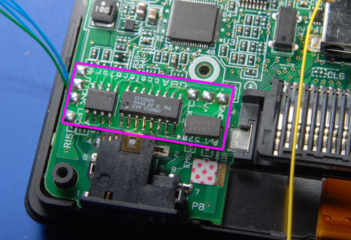
Make the remaining wiring connections as shown in the diagram. Be careful not to hold the soldering iron on any connection for too long or you could lift the pad from the DSAccelerator or DS board.
|
GBAccelerator DS Lite Back Connections
|
|
| GND | GBA cartridge slot pin 32 |
| V+ | GBA cartridge slot pin 1 |
| CLK | Solder pad where xtal used to be |
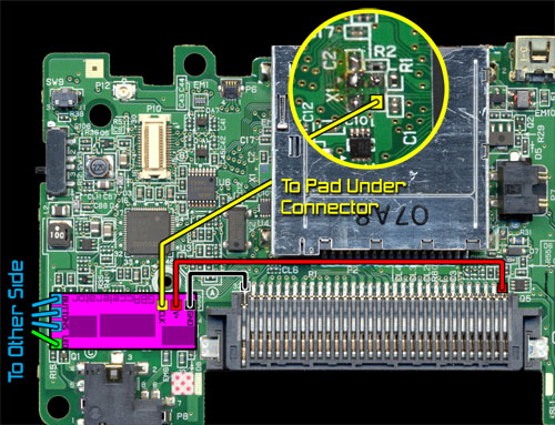
Once you are done you will (or at least should) end up with something that looks like this:
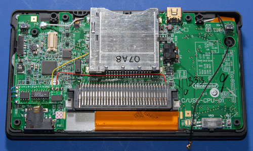
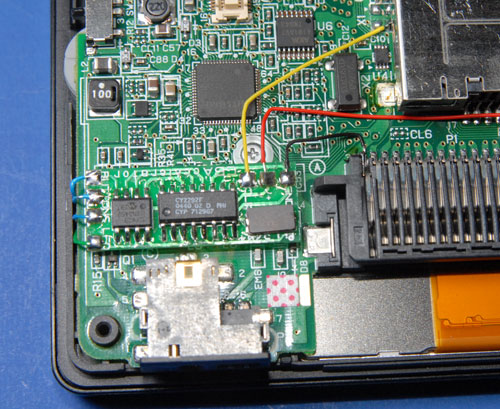
If your installation looks different, go fix it!
Put the DS Lite Back Together
Now you need to make a little extra room in the back cover for the chip you just added. Remove the three screws that hold the stylus channel onto the back cover.
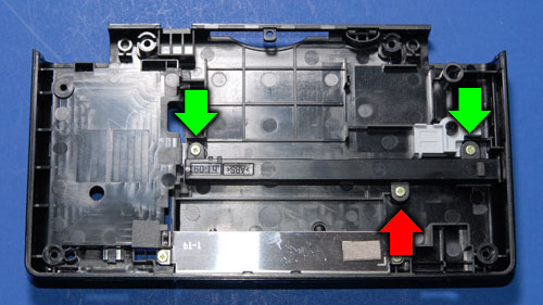
Remove the stylus channel. Use a utility knife to trim off the middle screw tab (the one that had the red arrow pointing to it).
Re-install the channel, but remember now you only need two screws. Save the third one for your next project.
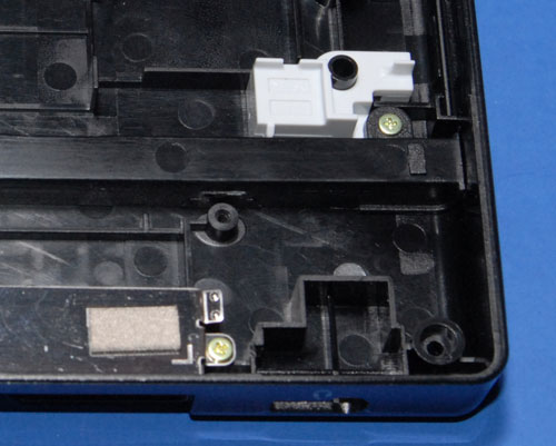
Reinstall the RF module onto the DS Lite PCB.
Run the black antenna wire back under the slot assembly and connect it to the RF module.
Very carefully put the L and R buttons (including their pins and springs) back into place.
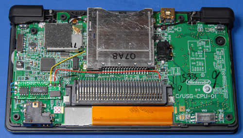
Gently lower the back cover onto the rest of the DS Lite. It should sit back down into position without requiring much force. If it feels like something is hitting the GBAccelerator chip, use needle-nose pliers to gently scoot the chip around until it is out of the way.
Replace the remaining screws that hold the back cover on.
Replace the two rubber feet that you had to remove.
Reinstall the battery.
Reinstall the battery cover.
(You probably want to leave the stylus and cartridge-plugger thing out so you can play.)
Flip the handheld over, put a game in and open the screen because it’s time to test out your handiwork!
Testing Out Your Handiwork
Turn on the DS Lite. It should boot just like you hadn’t spent the last hour or ten modifying it.
Start whatever game you inserted. It should look pretty normal too.
Press L, R and Select. Your game should start running faster now, and the power LED should start blinking to indicate that you are in “fast” mode (1.4x).
Press L, R and Select again. The game will go even faster and the LED will double-blink to let you know that you are in “ultra” mode (1.8x).
Press the buttons again. Now your game will be running much slower and the LED will be fading in and out (“slow-motion” mode, .66x)
One more press of the magic button combination will bring you back to normal, boring 1x.
Congratulations, you now have an overclocked Nintendo DS Lite! You even have a part left over, which is usually a good sign that you did a project right.


August 8th, 2011 at 3:09 PM
I regard something truly interesting about your blog so I saved to fav.
October 4th, 2011 at 9:55 AM
It works on Nintendo DSi?
October 20th, 2011 at 4:05 AM
definitely amazing posting, cheers
October 22nd, 2011 at 11:50 AM
This article shows how you can overclock or underclock Nintendo’s latest handheld console, the DS Lite. The mod allows you Do this by flipping the black part of the connector up and sliding the ribbon out. Small Ribbon .
December 27th, 2011 at 3:19 PM
Fantastic goods from you, man. I have understand your stuff previous to and you’re just extremely excellent. I actually like what you’ve acquired here, certainly like what you’re saying and the way in which you say it. You make it entertaining and you still care for to keep it sensible. I cant wait to read far more from you. This is actually a great website.
April 12th, 2012 at 3:28 AM
I actually found everything that I was looking to get. wonderful article, thank you
August 9th, 2012 at 6:27 PM
Hi, how are things? I recently discussed this post along with a coworker, there was a good laugh.
August 16th, 2012 at 6:43 AM
Valuable info. Fortunate me I found your site accidentally, and I’m shocked why this accident did not came about earlier! I bookmarked it.
August 19th, 2012 at 10:32 PM
Greetings! I know this is kinda off topic but I was wondering which blog platform are you using for this website? I’m getting sick and tired of WordPress because I’ve had issues with hackers and I’m looking at options for another platform. I would be awesome if you could point me in the direction of a good platform.
August 23rd, 2012 at 11:15 AM
Hi, i think that i saw you visited my site so i came to “return the favor”.I am attempting to find things to improve my web site!I suppose its ok to use some of your ideas!!
August 27th, 2012 at 11:27 PM
Deference to op, some good selective information.
September 2nd, 2012 at 10:55 AM
I wanted to put you the bit of note so as to say thanks as before on the beautiful strategies you’ve contributed on this website. It was really wonderfully open-handed of you to convey easily exactly what a few individuals might have offered for an electronic book to make some dough for themselves, precisely since you might have done it in the event you decided. The things in addition served to become a good way to understand that the rest have similar dream much like my very own to find out very much more pertaining to this problem. I’m sure there are many more enjoyable times in the future for folks who looked at your blog post.
September 4th, 2012 at 8:02 AM
I’m impressed, I must say. Really not often do I encounter a weblog that’s both educative and entertaining, and let me let you know, you’ve got hit the nail on the head. Your concept is outstanding; the problem is something that not enough people are speaking intelligently about. I am very glad that I stumbled across this in my seek for one thing regarding this.
September 4th, 2012 at 9:34 AM
This will be a excellent web site, will you be involved in doing an interview about how you designed it? If so e-mail me!
September 4th, 2012 at 5:42 PM
That might be this sort of an amazing cleverness that will you might be featuring so you make the idea separate pertaining to free of cost. My spouse and i take pleasure in visiting website pages that will figure out your appeal involving presenting a new superior quality power source pertaining to 100 % free. It is your classic everything that round shows up near process .
September 19th, 2012 at 8:43 AM
I think this is one of the most important information for me. And i’m satisfied reading your article. However should observation on few normal issues, The site taste is perfect, the articles is in reality great : D. Excellent job, cheers
May 3rd, 2013 at 10:24 PM
Hello to every body, it’s my first visit of this blog; this web site carries amazing and really excellent material designed for visitors.
June 15th, 2013 at 2:42 PM
Some genuinely excellent blog posts on this internet site , regards for contribution.
July 12th, 2013 at 9:00 AM
I have to say that for the last couple of hours i have been hooked by the impressive posts on this blog. Keep up the good work.
July 20th, 2015 at 12:44 AM
Tried this on the weekend, it’s easier than it looks to implement and some of the games are amazing running at the higher speeds, a lot of fun! Thanks, Tom
February 1st, 2016 at 4:40 PM
This is so much fun and the games are running smooth under increased speed. Both Tetris and Super Mario are amazing with this particular overclocking mod =)
February 12th, 2016 at 11:15 AM
Great Mod, there are tonnes of title that this would make amazing
July 10th, 2016 at 10:35 AM
I prefer the sign NO ENTRY to the one that says NO EXIT.
September 30th, 2016 at 11:12 AM
you are really a good webmaster. The website loading speed is incredible. It seems that you’re doing any unique trick. Furthermore, The contents are masterpiece. you’ve done a great job on this topic!
February 8th, 2017 at 3:06 PM
Love the mod, thats pretty much my weekend mission now, thanks!
March 14th, 2017 at 5:03 PM
Sick mod still
July 20th, 2019 at 9:13 PM
I have noticed you don’t monetize modd3d.com, don’t waste your traffic,
you can earn additional bucks every month with new monetization method.
This is the best adsense alternative for any type of website (they approve all websites), for
more info simply search in gooogle: murgrabia’s tools
September 6th, 2019 at 9:02 PM
It’s remarkable to go to see this web page and reading the views of all colleagues regarding this paragraph, while I am also eager of getting experience.
February 1st, 2021 at 3:39 PM
Hi, I am attempting this, but I am having trouble removing the X1 chip because it is so small. Any tips?
February 2nd, 2021 at 11:45 PM
nvm, I just burnt off the X1 chip with my solder, and then proceeded to tools to break it off.
March 16th, 2025 at 2:11 AM
An excellent mod/kit that I purchased in the mail from your website. Purchased a second DS Light and a second known working motherboard to complete the mod on. Looking forward to use this high tech mod while playing Mario Kart as normal speed of the CPU is controlled by the crystal X1.
Thank you again for supplying such a wonderful pre made mod kit to the public.
March 16th, 2025 at 2:21 AM
An excellent mod/kit that I purchased in the mail from your website. Purchased a second DS Light and a second known working motherboard to complete the mod on. Looking forward to use this high tech mod while playing Mario Kart as normal speed of the CPU is controlled by the crystal X1.
Thank you again for supplying such a wonderful pre made mod kit to the public. Here is a soldering TIP from a Professional Diagnostic Technician- Find someone that has a hot air rework machine with a very small tip to concentrate hot air to carefully/ correctly remove X1 crystal from the motherboard. Using Kapton tape which is heat resistant around component X1 to prevent other surface mount SMT parts from being blown off of the motherboard. Hope this helps others that would like to complete this mod on their Nintendo DS Lite.