Overclock Your Game Boy Micro
Game Boy April 5th, 2007A few people have written me asking if it is possible to overclock a Game Boy Micro. After all, that is the only GBA variant left to mod. The short answer is “yes!”. It’s not ideal, however. The first problem is that the power LEDs on the Micro don’t stay on all the time, so you can’t use them to indicate which mode the GBAccelerator chip is in unless you add extra parts to invert the LED output or rewire them completely. The biggest problem is that the Micro is so small that the GBAccelerator chip barely fits inside. It does fit on top of the CPU, but that puts some pressure on the back of the LCD and makes me a little bit nervous about damaging it.
If you are one of those people that can’t stand not modding something, then I say go for it.
What you need:
- Game Boy Micro
- GBAccelerator overclocking chip
- Tri-Wing screwdriver
- Small Phillips screwdriver
- 30 AWG kynar wire-wrap wire
- Low-wattage, fine-tipped soldering iron
- Fine, rosin-core solder
- Wire cutters
- Wire stripper
- Needle-nose pliers
- Double-sided tape
- Cup or bowl to contain parts
Disassemble the GBA-Micro
Start by using a phillips screwdriver to remove the battery conver. Set it aside.
Pull the battery out. Disconnect it by grabbing onto both wires and pulling. Set the battery aside.
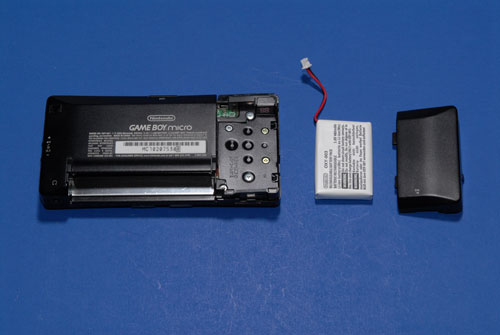
Inside the battery compartment are two silver tri-wing screws. Remove them and place them into your parts container.
Along the top and side edges are four small black tri-wing screws. Remove them. They are smaller than normal Nintendo tri-wing screws, so you may have to push hard to get them out.
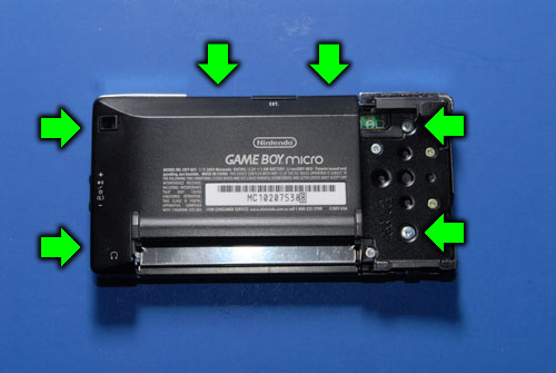
Lift the back cover off and set it aside.
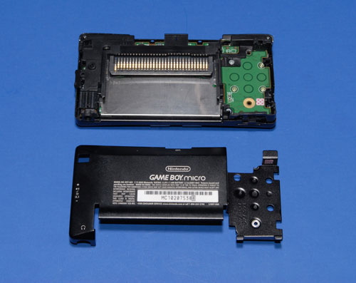
Remove the three silver Phillips screws that hold the black plastic piece on.
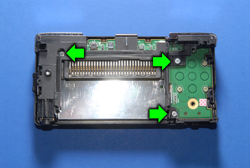
Lift off the plastic piece, being careful not to lose the volume control button piece.
Remove the silver L and R buttons.
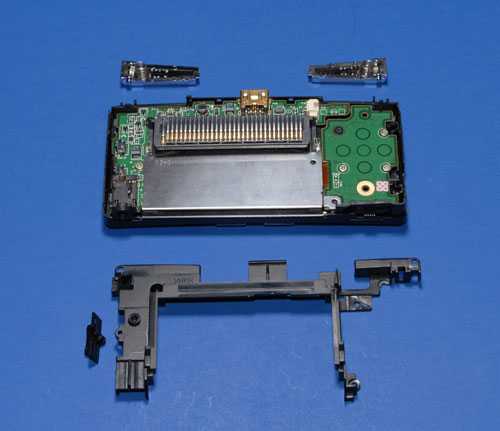
Remove the four gold-colored Phillips screws that hold the PCBs down.
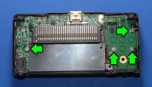
Carefully start prying the PCBs out of the case. You will find that the main half won’t come completely free because it has several ribbon cables attached to it. Detach the two ribbon cables that go to the LCD by lifting up on the dark gray part of the connectors. Once this latch has been flipped up the ribbons will slide right out.
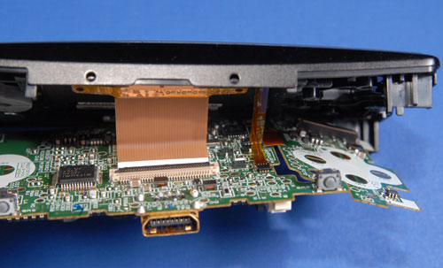
There is no way to disconnect the ribbon that goes to the select/start button board, but the board will slide out of the corner it is wedged into. Do this now, being VERY CAREFUL not to pull on the ribbon cable itself. It is very FRAGILE! Please don’t ask me how I know this.
The boards should come completely free from the case now. Go ahead and pull it out and pull off the metal plate that goes under the game cartridge. Try not to dump out all the buttons, button pads and speaker parts from the front half of the case.
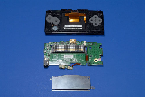
Install the GBAccelerator
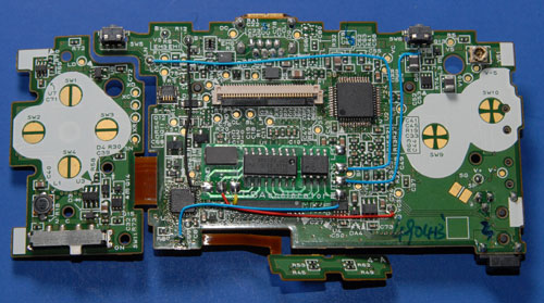
Remove Crystal X1. You may be able to desolder it, or you may have to pry it free with a pair of pliers. Be very careful not to damage any other components if you have to get violent with it.
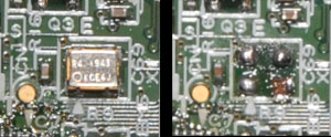
Solder a wire to the point indicated (solder pad where the crystal used to be). You have to do attach this wire before you put the GBAccelerator chip in place because it ends up underneath it.
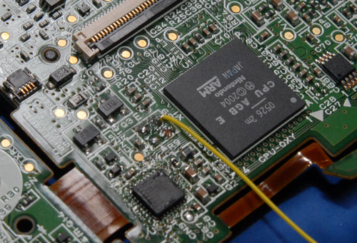
Use a small piece of double-sided tape to stick the GBAccelerator chip to the top of the Micro’s ARM CPU in the position indicated. Attach the other end of the CLK wire now.
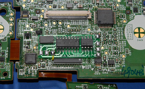
Make the rest of the connections as indicated in the diagram. Note that the LED output on the GBAccelerator doesn’t get connected.
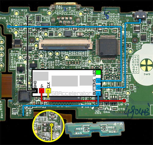
When you’re all done it will hopefully look like this:
Reassemble the GBA-Micro
Putting it together is just like taking it apart only backwards.
Testing
Turn the Game Boy on. If all went well it should turn on like normal. To cycle through the different speeds, press L, R and Select at the same time then release them. There is no LED to tell you what speed you are in, so you’ll just have to judge by how hard your game is.


January 29th, 2013 at 1:11 PM
Hello! I just wanted to tell you that I really enjoyed going through your blog posts.I will certainly bookmark it and suggest it to all of my friends. I am sure they will enjoy visiting your web site. Would you be able to recommend any other blogs and/or forums that handle similar topics? Thank you in advance!
October 21st, 2013 at 6:44 AM
Thank you for these precise explanations.
I just can’t figure out how you managed to put back the small ribbon that goes to the lcd. The large one has a hard part that makes it easy to put it back, but for the small one it’s just impossible…
October 22nd, 2013 at 9:23 AM
I have some long smooth needle nose pliers that help.
July 2nd, 2022 at 3:42 PM
Hi, i was searching a way for fixing my gbm and came across yout blog. Interesting post. However i was wondering if you know points to fix the ribbon cable that connects the dpad/power to the main board. My lcd light flickers when i moce the flex and UP and DOWN are not working on the dpad.
July 6th, 2023 at 1:51 AM
Loking for GBM motherboard schematics diagram. Any chance to have something?