Build A USB Car Charger
Phones July 21st, 2006More and more portable devices connect to their chargers via mini-USB 2.0 connectors. In this article I’ll show you how to build a car charger for your Blackberry, Pocket PC, phone, PSP, bluetooth headset, etc. out of junk you probably already have lying around your house.
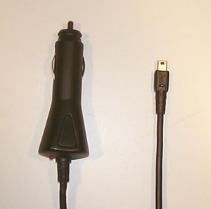
The theory behind this mod is simple; a 7805 voltage regulator drops the 12-13.8 volts coming out of your car’s cigarette lighter receptacle down to the 5 volts required by USB devices.
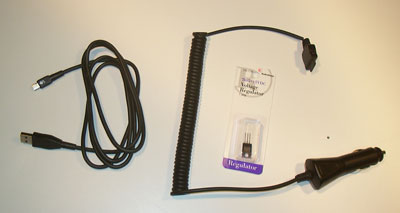
Parts Needed:
- Cigarette lighter plug (the car charger from that old analog cell phone you’re tired of looking at will do nicely)
- USB cable with mini-USB 2.0 connector on one end (so many devices come with these now you’re bound to have an extra somewhere)
- 7805 +5V Fixed-Voltage Regulator (you’ll probably have to go buy this one. Radio Shack has them for $1.59)
Tools Needed:
- Soldering Iron, solder, etc
- Screwdriver (if needed to take apart your cigarette lighter plug)
- Needle-Nose Pliers
- Wire Cutters
- Utility Knife
- Multimeter
- Hot Glue Gun
Start by disassembling the cigarette lighter plug. Remove all the guts and set them aside.
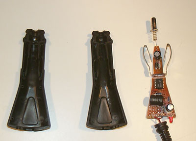
Cut or desolder tip and side contacts from circuit board if needed. You should now have a hollow shell and two sets of contacts.
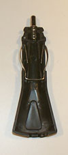
Next you’ll need to prep the USB cable. You need to find out which wires goes to the power pins on the mini-USB connector. Most of the time it will be the red and black ones, but some cables may be different. If this is the case, cut the insulation away from a section of the cable, but don’t cut any of the wires yet. Plug your cable into a computer or charger or something that will put power on the cable. Use your meter to locate the wires that have 5 volts across them. Also note the polarity.
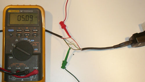
Once you know what two wires you need to connect the 5 volts to in your USB cable trim off any excess wires and connectors. You should now have a cable with a mini-USB connector on one end and two wires sticking out of the other.
Now it’s time to start soldering everything together. The way your cigarette lighter plug is built and how much room you have in it will determine exactly how everything is laid out, but electrically you should end up with this:
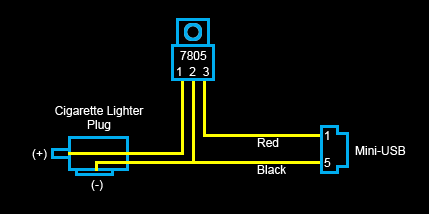
If you have any parts or contacts that just won’t stay put because you yanked out the PCB that was supporting them or they are just being difficult, use some hot glue on them.
(It’s hard to see all the parts in this picture; use the schematic to figure out how to connect everything)
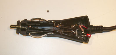
If you want, you can install an LED in the cigarette lighter plug. Hook it up in series with a 250-ohm resistor across the 5v output of the voltage regulator (pin 3) and ground (pin 2).
When you’re done, all the components should fit inside the case of your plug and all the contacts should be in their proper places. The USB cable should come out the end of the plug where the original one did (bonus style points BTW for using the stock strain-releif). If everything looks good go ahead and put the plug back together. Since no external modifications were made to the plug it should look like it was born as a USB car charger.
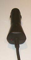
Take your charger to the testing lab (car). Plug it in. If you installed an LED, look and see what it does. If it doesn’t come on at all you probably didn’t hook something up right. If it gets really bright for a second then melts, you probably didn’t hook something up right. If it comes on and stays on, congratulations, you have hooked up the voltage regulator correctly.
This next step is a test of bravery. If you are brave you can connect one of your precious portable devices to the charger and see if it charges. If you are not brave (or are perhaps just smart) you can test the voltage coming out of the mini-USB connector. If it reads about +5v, go ahead and plug it in!
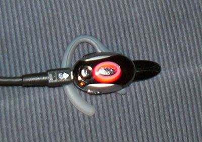
The red light means it’s working!


September 12th, 2011 at 1:40 PM
There would be nice to put at least 0.5uF capacitors on INPUT and OUTPUT (I put 4.7uF):
– between 1-2 (of 7805)
– between 2-3 (of 7805)
September 14th, 2011 at 3:12 PM
Also you need pull up resistors on both data lines.
October 26th, 2011 at 7:42 AM
hey this is just the information I was trying to find, can you mind only discuss it together with my visitors ?
January 14th, 2012 at 7:43 PM
Really good blog, thank you so much for taking the effort to write this post. This site is very informative. Keep up the good work.
October 1st, 2012 at 6:45 AM
really coool information…I am trying to know the circuits of many such devices..Thanx buddy.
December 18th, 2012 at 1:24 PM
I have this working with salvaged parts LF50AB(V) (LM2940CT should be ok to) I only used 2.2uF cap on output no pull down resistors, FYI if you have a newer blackberry (9300 mine) that complains of the pc being in sleep mode, or says the source cannot charge your blackberry then short pins 3 & 4 of the USB socket. Peeps be careful of the heat of the voltage regulators commercial units use DIP 8 34063AP1 or similar that dont generate so much heat as the TO used here. Great article after reading this I had found parts and built in less that 30 mins inc salvaging time 🙂
June 4th, 2013 at 9:03 AM
Thank you for your time taken to display this info. I have been reading other sites regarding this subject but yours seems to be the most on topic. have you got a facebook account? i can send my users to your site to read about this.
July 5th, 2013 at 10:53 PM
Thanks designed for sharing such a nice thought, paragraph is pleasant, thats why
i have read it entirely
July 11th, 2013 at 3:32 AM
It’s actually a nice and useful piece of info. I’m happy
that you simply shared this helpful info with us.
Please keep us informed like this. Thank you for sharing.
May 30th, 2015 at 6:52 AM
The 7805 IC is really bad for this task. It will waste about 60-70% of power, and dissipate it as heat. When supplying just 1A the it will generate 8 watts of heat, and the TO220 package can only dissipate 1,5W of heat without a radiator!
If you can spend a little more money, you can use a buck converter instead of 7805. The buck converter will only waste about 10-20% of power, so while drining 0,5A at the input it will supply about 1,2A at the output, without even getting warm. Of course the buck converter will need a few external components, but it’s much more efficient and won’t generate a lot of heat.
The 34063 buck converter is just as cheap as 7805, and it only needs a few resistors, an inductor and a Schottky diode to work.
If you really want to use 7805, you should at least add a couple of ceramic and electrolytic capacitors from input and output to the ground, otherwise the output will be a little noisy.
August 3rd, 2015 at 6:07 AM
I really enjoy looking at on this web site , it holds excellent blog posts. “Dream no small dreams. They have no power to stir the souls of men.” by Victor Hugo.
January 28th, 2017 at 5:51 AM
Thank you for the sensible critique. Me & my neighbor were just preparing to do some research on this. We got a grab a book from our local library but I think I learned more clear from this post. I am very glad to see such fantastic information being shared freely out there.
March 12th, 2017 at 12:20 PM
“Very good post.Thanks Again. Want more.”
March 25th, 2017 at 4:08 PM
“Im obliged for the article post.Thanks Again. Really Great.”