Multiplex LEDs with Fewer I/O Pins
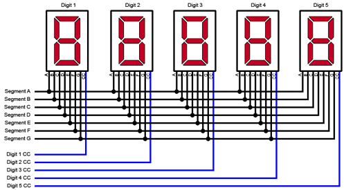
Electronics June 12th, 2007Multiplexing an LED display is a great way to cut down on the number of I/O pins you need to use on your microcontroller, etc. to drive the display. If you are using standard common-cathode 7-segment numeric displays, for example, you would hook the CC from each digit to a separate I/O pin, then connect each group of like-segments to their own I/O pin. If you had 5 digits, you would need 12 I/O pins instead of the 36 you would need if you connected each LED separately.
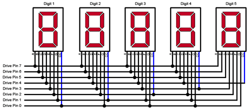
The great thing about LEDs is that since they are diodes they only light when the current flows in one direction. You can use this fact to cut your I/O pin count down even further. In our 5-digit example above you would only need 8 pins!
Normal Multiplexing:

This method is sometimes called “Charlieplexing”, named after the fellow (Charlie Allen) over at Maxim who wrote an application note about it.
Charlieplexing:
The trick lies in the fact that each I/O pin on your microcontroller can be driven high, low or Hi-Z. Each pin can be used to drive a group of segments and a digit’s common cathode (or anode), depending on its polarity.
Just drive the right combinations of pins high, low or Hi-Z (set it as an input) to light the desired segment. For our example the combinations would look like this:
|
L (CC)
|
H (A)
|
H (B)
|
H (C)
|
H (D)
|
H (E)
|
H (F)
|
H (G)
|
|
|
Digit 1
|
0
|
7
|
6
|
5
|
4
|
3
|
2
|
1
|
|
Digit 2
|
1
|
7
|
6
|
5
|
4
|
3
|
2
|
0
|
|
Digit 3
|
2
|
7
|
6
|
5
|
4
|
3
|
1
|
0
|
|
Digit 4
|
3
|
7
|
6
|
5
|
4
|
2
|
1
|
0
|
|
Digit 5
|
4
|
7
|
6
|
5
|
3
|
2
|
1
|
0
|
Note: Set pins not listed as High or Low as inputs (Hi-Z).
Your schematic will look different depending on how many digits/segments you are driving. Here are the basic steps for creating your schematic:
- Figure out how many drive pins you will need. This will be one more than either the number of digits or the number of segments per digit, whichever is greater. In our example we only had 5 digits, but we were using 7 segments. Therefore we needed 8 pins.
- Start drawing your diagram. Draw the digits across the top and however many drive lines horizontally across the bottom.
- Connect the CC (or CA) pins from each digit to a drive line. Make sure each digit is connected to one and only one drive line.
- Now start with your first digit and connect all the segments to drive lines. Be sure to skip the one that already has the CC for that digit connected to it. Other than that, order doesn’t really matter.
- Connect the individual segments for the remaining digits just like you did for the first one.
- Once you are done, make a chart that lists what combination of pins is required to drive each segment. You will need this when you are writing your software.
That’s it! You are still multiplexing your display, lighting it one digit at a time, but you are using the power of the diode to do it using fewer pins.


March 25th, 2013 at 5:25 AM
I do believe all of the concepts you’ve introduced in your post. They’re really convincing and can certainly work. Nonetheless, the posts are very quick for novices. May you please prolong them a little from subsequent time? Thanks for the post.
February 17th, 2014 at 5:45 PM
Hi,
I’m trying this trick using BJT on common cathode, since PIC-pin supplies only 20mA. In fact, in the case of all 7seg lit, we need 140mA… any idea to do it?
I’ve found some schematic working on common anode 7seg… but I have common cathode. 🙁
Using your configuration, I don’t find any solution using BJT (NPN) in common emitter mode.
February 18th, 2014 at 3:30 PM
The schematic above is for common cathode, so it should work for you. Really, CC and CA would get wired the same way. The only difference is the high/low signals coming out of the microcontroller need to be inverted for one or the other. If you’re working off of another schematic that shows common anode, just wire everything up the same but use the logic in the chart above as it is for CC.
As far as transistors go, you’d be adding complexity that Charlieplexing is supposed to take away. You’d need two transistors for each line you’re driving (one for high and one for low, and turn both off for hi-z). If you drive them all separately then your pin count on your microcontroller goes up again. You could probably work the resistors so that you could drive the pair with one pin and still get your 3 states coming out of them.
I’d recommend just hooking the displays right to the microcontroller, then multiplexing them so that only one (or two, or how many ever; don’t forget that there’s a chip maximum on current too) segment is on at a time. This solution moves some of the complexity to the software side, and is way simpler in hardware (which is what I assume you’re after since you’re Charlieplexing to begin with). As you cycle through which segment gets turned on, make sure you keep the timing the same whether segments are on or off, otherwise you get that weird thing that 80s electronics used to do sometimes where the more segments turned on, the dimmer they all got.
Happy multiplexing!